Understanding Energy Distribution in Horns System
When it comes to horns, the energy distribution across frequencies is a crucial factor as a horn is an energy distribution device.
This article explores how the driver itself and the horn interact to shape this energy distribution.
The overall balance and brain
Adapting Directivity to the Listening Distance
We listen at a so-called critical distance where the direct field (sound coming directly from the speaker) and the reverberant field (sound reflected from the walls) are in a 50/50 or 60/40 balance. The reverberant field is composed of off-axis radiation that returns to the listening position even when we are directly in front of the speaker, due to wall reflections. These reflections are effectively merged with the initial direct field.
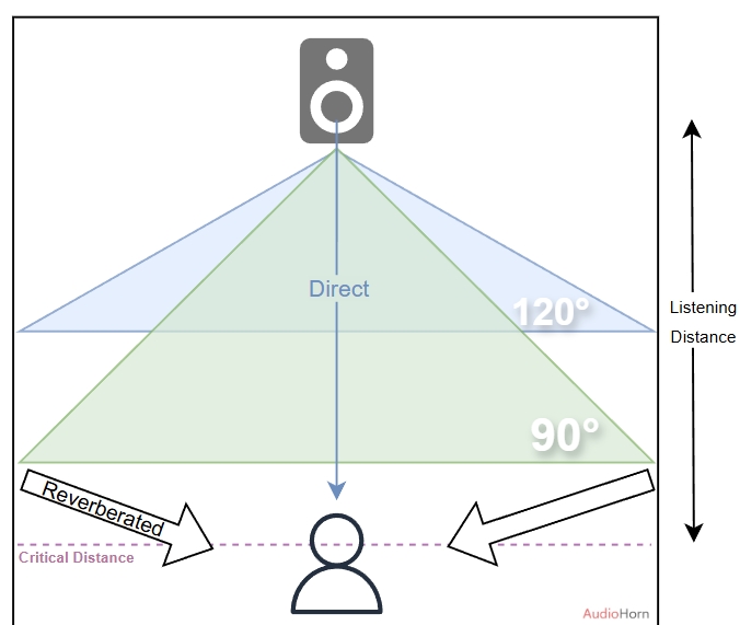
This balance means we must adapt the coverage angle to the listening distance, rather than follow a “one opening fits all” 120° approach typically used in control rooms or recording studios.
These professional sound environments are extremely damped, intentionally prioritizing control over soundstage. In a living room, however, the goal is to create a wide and natural soundstage in a less damped, more lively acoustic space.
A coverage of about 90° horizontally and ~60° vertically better matches these conditions, taking into consideration listening distance, room acoustics, and even room shape, thanks to the narrower vertical dispersion compared to the horizontal one. For a tweeter waveguide, achieving such coverage, which is narrower than the tweeter’s natural radiation over most of its bandwidth, requires a more advanced solution.
Energy Balance and Perceptual Effects
In practice, when we perceive a sound as aggressive at high volumes, an imbalance between treble and the rest of the spectrum as we move further from the speaker, or a lack of impact, it is likely due to two factors:
- An imbalance between the direct field, aka on-axis sound, and the reverberant field, aka off-axis radiation that returns due to wall reflections
- An imbalance in the energy radiated and perceived by the ears across the full frequency spectrum of the speaker
If the coverage of our speaker is too wide in the upper half of the spectrum, where directivity control is most perceptible, we end up with too much reverberant energy compared to the direct field, and globally too much energy in the upper range of the speaker relative to the lower range.
Our ears are particularly sensitive to the upper midrange and treble frequencies, where sound is more likely to damage the hearing system. Excessive energy in these regions can lead to fatigue, discomfort, and even long-term hearing damage. More details in our audibility article.
To prevent this, our brain instinctively limits the volume when the sound becomes too intense in this area — it’s an internal psychoacoustic SPL limiter.
Too much radiated energy in the upper range reduces our ability to increase the overall level comfortably.
Balancing the energy between the midrange, low midrange, and high frequencies helps mitigate this issue and allows for higher usable SPL.
This ability to listen at higher SPL, thanks to a better balance between reverberant and direct fields — and between each part of the frequency spectrum — is what creates the sense of impact or kick.
It explains why “kick” is easy to achieve outdoors but harder to reproduce in small or medium-sized rooms. This is why using the right constant-directivity coverage for our horn is essential, instead of following the 120° trend.
A well-balanced energy distribution allows our brain to “authorize” higher volumes without triggering the pain or fatigue response.
In contrast, direct-radiating loudspeakers or 120° designs, which typically disperse sound over a wider area, create uneven sound fields that are more prone to causing fatigue due to over-radiated energy in the upper range, depending on listening distance and acoustics. This limits maximum SPL, reduces the sensation of kick, and results in a less balanced sound.
Final Thoughts
By using a loudspeaker with constant directivity and optimizing our room acoustics, you can enjoy a more balanced and immersive listening experience, even at higher volumes, with greater impact in the low end of the spectrum.
This approach is not new — it’s how professional acousticians design Home Theaters or personal listening setups, aiming for a comfortable listening experience, a wide soundstage, and strong impact in the low end.
To truly take our sound reproduction to the next level, it’s essential to use solutions adapted to the specific situation at hand, rather than simply applying approaches developed for a completely different environment and purpose.
The Driver’s Role
The energy a compression driver produces is determined by several factors:
-
Diaphragm Size: Larger diaphragms naturally produce more low-frequency energy, but their breakup can impact very high frequencies .
-
Motor Characteristics: The motor’s sensitivity and resonance frequency (Fs) as other characteristics influence the overall energy output and roll-off at low frequencies.
The Horn’s Influence
The horn plays a significant role in how energy is distributed:
- Loading:
Horns act as a load on the driver, affecting its response at different frequencies. This loading effect is most prominent at lower frequencies and diminishes significantly as we move up the frequency range.
More details here: acoustic loading
- Horizontal and vertical directivity:
The horn’s directivity pattern, both vertical and horizontal, significantly influences on-axis energy. Decreasing horizontal coverage helps retain more energy on-axis.
Reducing vertical coverage redirects some off-axis energy back toward the on-axis region. However, it’s important to note that reducing vertical directivity improves sensitivity only within the bandwidth where vertical and horizontal coverage overlap.
As the horn’s mouth height decreases, vertical control is lost earlierb than horizontal one. When vertical control is lost but the horn is still in use, the overall loading is affected because a portion of the energy escapes vertically uncontrolled in the low end.
The throat defines the end of directivity control, a parameter to consider with large AMT drivers, where a tall vertical throat limits the vertical control of the waveguide.
Ultimately, when both horizontal and vertical control are lost, depending on the horn mouth size, the horn cannot benefit from loading, setting an absolute limit on the potential loading effect.
- Constant Directivity:
Horns designed for constant directivity, which maintain a consistent sound dispersion across a specified angle, redirect part of the energy off-axis. This means that energy redirected off-axis is no longer present on-axis.
This can be seen with the high frequency roll off of a compression driver horn, where this behavior helps preserve the intended directivity pattern.
With a tweeter mounted in a waveguide, since the natural tweeter radiation is wider than a typical 90° waveguide, more energy is directed on axis as the frequency decreases when a 90° waveguide is used. When the wavelength becomes smaller than the waveguide, the tweeter’s own radiation pattern dominates and produces a natural directivity slightly below 80°.
For a good listening experience, psychoacoustic studies provide a general guideline: constant directivity should be maintained up to approximately 7–8 kHz minimum, then can gradually decrease above this range.
More details in our Constant directivity article.
The interplay between driver characteristics, horn loading and horn directivity creates a phenomenon known as the “bell response” that is explained in Horn Response article.
High Frequencies and Physics
Physics dictates that horn loading has minimal impact on very high frequencies, as it’s related to acoustic loading.
In this region, the driver’s motor characteristics become the primary determinant of energy output as, on best horn about loading, loading is inversely proportional to frequency and ends when horn’ control ends.
The effect of acoustic loading (aka the “loading effect”) is inversely proportional to the frequency.
Horn Low-End Roll-Off
The driver’s motor naturally starts to produce less energy at lower frequencies, depending on its characteristics and diaphragm size.
This reduction in motor output, combined with the decreasing horn loading effect at low frequencies, contributes to the natural roll-off in low-end response. As the horn’s width becomes insufficient to maintain the wavefront, the directivity pattern widens significantly, marking the limit of the horn’s effective loading capability and resulting in a drop in sound pressure level.
At this point, the reactive load can no longer be effectively positioned within the horn’s directivity control band, and any attempt to increase loading will have little to no effect.
Horns with stronger reactive loading prior to this limit typically exhibit a sharper fall, which simultaneously produces an appreciable “free” SPL gain just above the cutoff, making them more effective in the low-frequency extension.
Below this point, any adjustment of the reactive load becomes ineffective, as both the motor limitations and the loss of directivity control combine to define the horn’s low-frequency boundary.
Don’t Waste Energy: Directivity and Efficiency
Adapting the horn’s directivity pattern according to the listening distance is not just about improving the listening experience.
It also allows us to respect the critical distance, the point where the direct sound from the driver and the reflected sound in the room reach a balance (around 50/50 or 60/40).
By maintaining constant energy directionality up to 7–8 kHz minimum with coverage adapted to the critical distance, we ensure efficiency while achieving clear and accurate sound reproduction.
This approach preserves the balance between direct and reflected sound within the critical distance.
This is where the concept of “midrange narrowing and beaming” comes into play. This phenomenon, although primarily affecting off-axis response, can also slightly impact the on-axis response, representing a loss of usable energy and contributing to an imbalance in sound reproduction.
More details can be found in the linked article: Midrange narrowing and beaming
A Note on Frequency Correction (EQ) and Phase Shift
As described here: How to implement my horn and my speaker, the proper way to correct the frequency response is using IIR (minimum-phase) EQ:
-
Minimum-phase filtering also affects phase, which is a positive feature. Wherever there is a peak or dip in frequency, the phase is impacted in the same way. An IIR EQ will therefore correct both the amplitude and phase responses simultaneously, in a beneficial manner. This phase response adjustment is necessary to help linearize the overall response.
-
FIR filtering (linear-phase filtering) should be used only for crossovers. When implementing a crossover, we aim to divide the frequency spectrum without affecting phase, which is exactly what FIR filtering provides. FIR should not be used for EQ, only for crossover.
Conclusion
The study of horns demonstrates that energy distribution is the key to both efficiency and perceptual quality. The interaction between driver characteristics, horn loading, and directivity determines how energy is radiated across frequencies and angles, directly influencing the on-axis and off-axis balance, and ultimately our listening experience.
Adapting the horn’s coverage to the critical distance ensures a proper balance between direct and reflected sound, allowing the brain to perceive higher volumes comfortably, maintain impact, sound stage, fidelity, and reduce fatigue.
Horns with better-managed directivity and loading allow higher SPL in the low and mid frequencies, while preserving energy balance.
Ultimately, achieving a balanced, immersive, and impactful sound requires selecting solutions that are adapted to the specific listening environment and purpose, rather than copying approaches developed for different acoustic conditions. Energy management, directivity, and psychoacoustic considerations are the foundation of a truly optimized horn system.
![]()